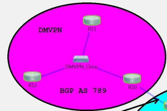
In this section of the lab build, I’m going to look at setting up DMVPN Phase 1 in the lab topology. The DMVPN area of the lab is a simple 3 router configuration, with R10 as our DMVPN hub, and R11 and R12 as the DMVPN spokes.

DMVPN Phase 1 is the simplest configuration for a DMVPN network, but it is also the least efficient in terms of how traffic traverses the DMVPN cloud. With a Phase 1 network, tunnels are only built between the hub and the spokes, meaning that all traffic between the spokes must traverse the hub. As we will see with the other DMVPN phases, dynamic tunnels can be created between the spokes in order to build direct communication between them.
Phase 1 with static routes
To first look at the basic interaction between the hub and spokes in the DMVPN network with phase 1, we’re going to use static routes to build our DMVPN network. In general, this wouldn’t be allowed in a lab environment, since any sort of static routing is generally prohibited, but it will give us an understanding of how traffic moves through this phase of the DMVPN network.
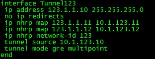
The first steps are to configure the hub and spoke communication over the DMVPN network. In phase 1, the hub is configured as a mGRE interface, and the spokes are configured as P2P GRE tunnels to the hub. For the hub (R10) configuration, this is the configuration I have used:

The first thing to do when we set up our Tunnel interface is to assign an IP address for this tunnel. Next, we specify the tunnel source, either using the IP address or the interface that connects us to the DMVPN cloud. We then specify the tunnel mode as mGRE, which is only configured on the hub in DMVPN Phase 1. This allows for the hub to establish DMVPN tunnels with multiple spoke sites. With Phase 1, we are setting up static NHRP mappings rather than dynamically learning the NHRP mappings, which we will do when we set this up using a dynamic routing protocol later. We use the command ‘ip nhrp map <tunnel-ip-address> <nbma-ip-address>’ to map the NBMA address, which is the IP address of the tunnel source, to the IP address of the GRE tunnel. The last step is to associate a network-id to this NHRP instance. This is mainly used when there are multiple NHRP domains (GRE tunnel interfaces) configured on a router. They are locally significant only, but it’s best practice and easiest to configure the same network-id on each router that is going to be a member of a DMVPN tunnel. There are other ways to use the NHRP network-id in multi-GRE configurations that will be discussed in later postings.
On the spoke routers (R11 and R12) the configuration is fairly simple as well. With Phase 1, we are simply creating a point-to-point GRE tunnel from the spoke to the hub. This is the configuration that I’ve set up on R11:

As you can see, the configuration is similar to the hub configuration, except that we specify the destination of the tunnel (the hub) and we create an NHRP mapping to the hub as well. The configuration is similar on both spokes, except that we change the local IP addresses.
Verification
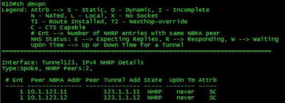
Once we have configured the DMVPN hub and spokes, we can use the ‘show dmvpn’ command to verify the DMVPN configuration on the hub and spokes. Here is the output on the hub:

As you can see, we have two NHRP peers on the hub, R11 and R12. The Peer NBMA address is the IP address of the interface that the GRE tunnel source of the remote end, and the Peer Tunnel address is the IP address of the GRE tunnel interface. The ‘S’ under the Attrib column indicates that these are static NHRP mappings. We can view the NHRP mappings configured by using the ‘show ip nhrp’ command:

At this point, we can ping between the GRE tunnel interfaces of all 3 routers. We can also see that in order to reach R11, R12 has to traverse through R10 (and vice versa):

It quickly makes sense why Phase 1 is an inefficient method for DMVPN tunnels, as all traffic between the spokes needs to pass through the hub router. In very large DMVPN deployments, this would put a large amount of strain on the hub, as it would have to encapsulate/decapsulate all of the overhead for the spoke-to-spoke traffic.
The last step in this is setting up static routes on our routers in order to reach the Loopback interfaces (and other networks) on each of our routers. On the hub, this is done by configuring static routes to the Loopback networks of R11 and R12, and pointing this to the DMVPN interface of the routers. On the spokes, we simply set up a default route to the hub, and then we are able to ping between the loopback networks on the hub and spoke routers. In the next post, I’ll be looking at setting up DMVPN Phase 1 with OSPF and EIGRP.

Very well explained, thank you
LikeLike
Pingback: VMware NSX, Figuring Out Intent-Based Networking, and Career Management in Gestalt Networking News 17.7 - Gestalt IT