Cisco Live 2017 – Reflections

Today is the final day of Cisco Live US, and like I’ve already tweeted out today, this is a bittersweet day every year. This has been the sixth time that I’ve attended Cisco Live, beginning with my first event in 2011 in Las Vegas. For some reason, it also brought about a sense of reflection for me about what this event has meant to me on not only a professional level, but on a personal one. To say that my life has changed over the past six years would be an understatement, but part of it has been because of this event and the people that it has helped to connect me to.

As a self described introvert, I spent my first few CLUS events lurking in the shadows. I had a Twitter account, and I followed people who I saw were making changes not only on the social media side of things, but within the industry itself. I’m not going to name drop here, but these were people who I always sat at the cool kids table and I felt like an outsider looking in. This comparison, I would come to learn, was not accurate. As I started to drop my walls of fear of rejection, and yes, i’m psychoanalyzing myself here, I found that these were people who were passionate not only about the same things that I was, but they were people who were so very inviting of everyone into the circles they were in and more than happy to talk and share their experiences and their wisdom with everyone.

Continuing on, I started to hear about a program called Cisco Champions in 2014 and 2015, and the same people who I held in high regard were a part of this program. I decided to put myself out on a limb and apply for this program and was accepted into it in 2016. My social skills in person, still very shy and introverted, started to go away when I would talk to more people who shared the same passions that I had. I started to find it more comfortable to engage with others, even if I wasn’t quite sure what I was doing. I know that I often had a sense of imposter syndrome, something that I still experience at times. But putting myself out there and feeling uncomfortable in social experiences was something that while difficult at first I discovered often led to opportunities that I never thought possible. I ended up getting involved with things like Tech Field Day and RouterGods, where I continued to meet more awesome and friendly people who I can now call friends.

This isn’t a technical post, but I think for the first time attendee to Cisco Live who feels like they need to stick around what makes them feel comfortable, I would highly suggest doing otherwise. What makes us comfortable doesn’t evoke change from within, it keeps us in the same places we’ve always been. Cisco Live is one of the best opportunities I’ve had to get outside of my comfort zone, and while I didn’t embrace it at first, I’ve learned all that is possible when I did get outside of what I used to find comfortable. I would wager that many of the people here have that same fear of opening up and putting themselves out there, because of long held fears of judgement from other people about them. My personal experience has been that these fears have been proven wrong every time, and I have found a community of people that inspire me.

Keep coming back to Cisco Live, remain engaged through Twitter, Spark, Slack, or whatever channels with the people you meet here. Start a blog, find an identity for yourself online and a way to brand yourself, and get outside the walls that you may have always lived in because they were comfortable. Become passionate about something and share it with the community, give back and help to lift up others, because in the end, that has been what this community has given to me. And hopefully I’ll see you at Cisco Live 2018 in Orlando next year.

TFDx at Cisco Live 2017 – Part 1 (Preview)

Today I had the pleasure and honor of being invited to be a delegate at Tech Field Day Extra at Cisco Live. This has become an annual tradition for Tech Field Day at Cisco Live and other vendor expo’s, and I was lucky enough to be included as a delegate this year. If you’ve never heard of Tech Field Day, make sure to check out techfieldday.com to learn more about it. Odds are, if you’re reading this post, you’ve heard something about it and know the usual format. During one of the normal TFD events, there are typically 4 vendors per day over a 2-3 day period. TFDx Day 1 was different, as it was eight hours that were solely dedicated to Cisco.

The major initiative that Cisco has rolled out over the past few weeks, and the major focal point of CEO Chuck Robbins keynote on Monday at Cisco Live was called The Network Intuitive. My takeaway from this initiative has been that Cisco is really focusing on software driven networking, and that was the main point that was driven home during TFDx. Cisco wants software to be the driving force behind change in the network, moving to a fully automated (their words) network that can provide secure intent driven networking that will evolve and allow for new technologies to be added to hardware without having to rely on the old ‘Rip and Replace’ when an unsupported feature you need became available in the past.

I will say that at first, I was skeptical of the possibility that software had become the main focus of Cisco. I also admit, this is out of ignorance and not understanding how Cisco had evolved the process of designing their ASIC’s and software from the bottom up, completely changing from a monolithic IOS, where you had a WYSWYG IOS that drove the hardware, to IOS-XE (and XR), which were more container based and could have features added as they were needed. But the underlying driver to all of this was the flexible ASIC that allowed for new features to be integrated at the silicon level and added as they were released, simply by upgrading the IOS or adding a feature set.

They also discussed many other features of the new SD-Access and Digital Network Architecture (DNA) platforms, which integrate Artificial Intelligence (AI) along with Machine Learning to create a controller fabric that brings a whole new level of security and policy driven network implementation that I found very exciting. Being able to apply policies such as QoS on an extremely granular level, and having them integrated at the ASIC is something we haven’t seen before.

There are many other things that Cisco touched on today with the DNA discussion, and I will be breaking them down as I post more blogs about this great presentation. We were lucky enough to have the best of the best when it came to presenters from Cisco. I can honestly say that there was not a single one that I didn’t get something out of, even if it was my brain hurting from the sheer amount of information that it was attempting to process. I’ll be reviewing the videos as they are available and compiling my notes and getting a more precise picture of what was discussed. You can also view those videos at the TechFieldDay website.

Building a CCIE Lab: DMVPN Phase 1 (Static Routes)

In this section of the lab build, I’m going to look at setting up DMVPN Phase 1 in the lab topology. The DMVPN area of the lab is a simple 3 router configuration, with R10 as our DMVPN hub, and R11 and R12 as the DMVPN spokes.
DMVPN
DMVPN Phase 1 is the simplest configuration for a DMVPN network, but it is also the least efficient in terms of how traffic traverses the DMVPN cloud. With a Phase 1 network, tunnels are only built between the hub and the spokes, meaning that all traffic between the spokes must traverse the hub. As we will see with the other DMVPN phases, dynamic tunnels can be created between the spokes in order to build direct communication between them.

Phase 1 with static routes
To first look at the basic interaction between the hub and spokes in the DMVPN network with phase 1, we’re going to use static routes to build our DMVPN network. In general, this wouldn’t be allowed in a lab environment, since any sort of static routing is generally prohibited, but it will give us an understanding of how traffic moves through this phase of the DMVPN network.

The first steps are to configure the hub and spoke communication over the DMVPN network. In phase 1, the hub is configured as a mGRE interface, and the spokes are configured as P2P GRE tunnels to the hub. For the hub (R10) configuration, this is the configuration I have used:
DMVPN hub config
The first thing to do when we set up our Tunnel interface is to assign an IP address for this tunnel. Next, we specify the tunnel source, either using the IP address or the interface that connects us to the DMVPN cloud. We then specify the tunnel mode as mGRE, which is only configured on the hub in DMVPN Phase 1. This allows for the hub to establish DMVPN tunnels with multiple spoke sites. With Phase 1, we are setting up static NHRP mappings rather than dynamically learning the NHRP mappings, which we will do when we set this up using a dynamic routing protocol later. We use the command ‘ip nhrp map <tunnel-ip-address> <nbma-ip-address>’ to map the NBMA address, which is the IP address of the tunnel source, to the IP address of the GRE tunnel. The last step is to associate a network-id to this NHRP instance. This is mainly used when there are multiple NHRP domains (GRE tunnel interfaces) configured on a router. They are locally significant only, but it’s best practice and easiest to configure the same network-id on each router that is going to be a member of a DMVPN tunnel. There are other ways to use the NHRP network-id in multi-GRE configurations that will be discussed in later postings.

On the spoke routers (R11 and R12) the configuration is fairly simple as well. With Phase 1, we are simply creating a point-to-point GRE tunnel from the spoke to the hub. This is the configuration that I’ve set up on R11:
DMVPN spoke config.JPG
As you can see, the configuration is similar to the hub configuration, except that we specify the destination of the tunnel (the hub) and we create an NHRP mapping to the hub as well. The configuration is similar on both spokes, except that we change the local IP addresses.

Verification
Once we have configured the DMVPN hub and spokes, we can use the ‘show dmvpn’ command to verify the DMVPN configuration on the hub and spokes. Here is the output on the hub:
sh dmvpn hub

As you can see, we have two NHRP peers on the hub, R11 and R12. The Peer NBMA address is the IP address of the interface that the GRE tunnel source of the remote end, and the Peer Tunnel address is the IP address of the GRE tunnel interface. The ‘S’ under the Attrib column indicates that these are static NHRP mappings. We can view the NHRP mappings configured by using the ‘show ip nhrp’ command:
show ip nhrp hub
At this point, we can ping between the GRE tunnel interfaces of all 3 routers. We can also see that in order to reach R11, R12 has to traverse through R10 (and vice versa):
trace R12 to R11
It quickly makes sense why Phase 1 is an inefficient method for DMVPN tunnels, as all traffic between the spokes needs to pass through the hub router. In very large DMVPN deployments, this would put a large amount of strain on the hub, as it would have to encapsulate/decapsulate all of the overhead for the spoke-to-spoke traffic.

The last step in this is setting up static routes on our routers in order to reach the Loopback interfaces (and other networks) on each of our routers. On the hub, this is done by configuring static routes to the Loopback networks of R11 and R12, and pointing this to the DMVPN interface of the routers. On the spokes, we simply set up a default route to the hub, and then we are able to ping between the loopback networks on the hub and spoke routers. In the next post, I’ll be looking at setting up DMVPN Phase 1 with OSPF and EIGRP.

Building a CCIE Lab: MPLS Core (part 2)

Well, I’ve had numerous comments and discussions with people who indicated that there was another way to enable MPLS on all of the interfaces in the core on my lab. I had planned on touching this in a later post, but since it’s on my mind now, I decided to put this post together to look at MPLS autoconfig.

MPLS LDP autoconfig is a method of allowing the IGP that is configured on the router to automatically enable MPLS LDP on all interfaces that are associated with the routing protocol that is configured on the device. Autoconfig is an option to use with both the OSPF and IS-IS protocols, but for this discussion, we’ll be looking at OSPF specifically.

How things are currently configured:
We currently have LDP configured on a per-interface basis on all of our P/PE routers in the lab. We can verify this by using the ‘show mpls interface <interface> detail’ command:
sh mpls int det
As you can see above, the IP labeling enabled (ldp): indicates that this is configured via Interface config, which means that we have enabled MPLS LDP on a per-interface configuration by using the command ‘mpls ip‘ at the interface configuration level. For the purpose of this discussion, i’m going to remove this command on all of the interface of my P-1 router and then enable MPLS LDP autoconfig under the OSPF process.

Disabling MPLS on the interfaces
This is a fairly simple process, it just involves going to each of the interfaces and running the ‘no mpls ip‘ command. When this command is run, we can see that LDP goes down on all of our interfaces via a syslog message:
syslog ldp down
We can also verify that MPLS is no longer running on any interfaces using the ‘show mpls interfaces‘ command, and we can verify that we no longer have any LDP neighbors with the ‘show mpls ldp neighbor‘ command.

Enabling MPLS autoconfig
Using MPLS autoconfig is something that I can see a place for, but I also personally prefer the granularity that enabling MPLS LDP on a per-interface basis provides. There may be cases in a lab situation, or a real world one, where you do not want LDP to be enabled on all of the same interfaces that your IGP is running on. But if you’re going to be running MPLS on all of the same interfaces that you are running your IGP on in the MPLS core, it makes sense to use autoconfig for the time savings that it gives you when turning up LDP neighborships.

The configuration is very simple, under the OSPF process, simply run the command ‘mpls ldp autoconfig [area <area ID>]‘. If you have a multi-area OSPF process, it’s best to specify the area associated with the interfaces that you are wanting to enable MPLS LDP on. After we run this command, we can see that our LDP neighborships are up again via syslog messages:
syslog ldp up
If we look at the details for the interfaces now, we can see that there has been a change to how LDP labeling has been enabled on the interface as well:
sh mpls int det IGP
We can see that the IP labeling enabled (ldp): now indicates that IGP config is what enabled the MPLS LDP on the interface.

Disabling MPLS LDP autoconfig per-interface
So, now we’ve enabled autoconfig via OSPF. But what if, as stated above, we need to have LDP disabled on an interface that autoconfig enabled it on? What if our lab indicates that we must use autoconfig for MPLS and that we can not have LDP enabled on a certain interface? In order to do this, we go to the specific interface that we need to disable MPLS autoconfig on and run the interface command ‘no mpls ldp igp autoconfig‘. This will disable MPLS LDP autoconfig for just this interface, while leaving autoconfig running for the rest of the interfaces that are part of the IGP process.
no mpls autoconfig
We can use the same commands as before to then verify that LDP is no longer enabled on this interface, although the previous syslog messages essentially verify this as well.

Conclusions
Hopefully this helps to show another way to enable LDP interfaces in our MPLS core. I hope to hear more input on these write-ups as I post them. Please, send me any comments or suggestions and I’ll try to touch on them in a future post.

Building a CCIE Lab: MPLS Core

Ok, I’ve decided to put together things that I’ve been studying for the best part of a year and build my own lab topology using VIRL. The unfortunate thing with VIRL is that I’m now limited to a 20 node topology, but I’ll make due with what I can for now and if needed, I may move to GNS3 for a larger topology in the future. Honestly, I don’t know why the 30 node option was removed, except that Cisco has now partnered with Packet to offer double the nodes of your license, but you have to purchase server time on their platform, which honestly seems shady and really has me considering something different in the future if things don’t change. But that’s beside the point of this first post, so moving forward.

Anyway, here is a picture of the lab that I’ve put together in VIRL, and I’ll be attaching a link if you’d like to the VIRL file at some point if anyone wants to download it and play around with it on their own.

Master-Lab-Full

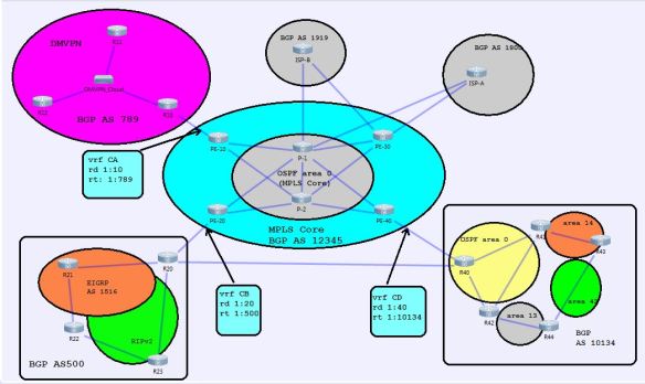
This is just the basic flow for now, and I have a feeling that it will be changing over time as I decide to test out different things.

MPLS Core, Step 1: IGP reachability
To begin with, I’m focusing on the configuration of the MPLS core of this, since it will be needed for communication between the sites. MPLS-Core

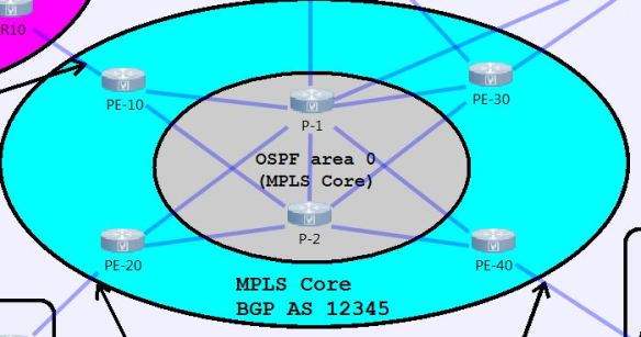
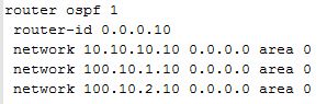
The core I’ve put together consists of 4 PE routers, along with 2 P routers. The IGP for the core is just a simple OSPF area 0. The first thing to do after everything is IP’d is to turn up OSPF on the six routers. I went with an OSPF PID of 1, and set the router-id for each router to 0.0.0.X, where X was the number of the router (0.0.0.1 for P-1, 0.0.0.10 for PE-10, etc). Network statements were in place for the point-to-point interfaces and loopback0 addresses. I used /32s for the loopback0 address since I was going to be using that as my MPLS LDP router-id as well.

Sample OSPF config for PE-10:

PE-10 OSPF config

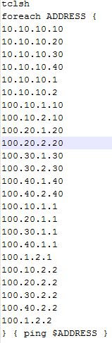
After OSPF is turned up, I ran a TCL script on each router to ensure that I could reach all points within the core from each router. Here’s the TCL script I use, it’s pretty good to get in this habit as I prepare for the lab, although the first run seemed to cause several of my lab routers to lock up and need to be rebooted. I think I had an incorrect statement in the script that I corrected, but it was definitely a reminder to save often.

TCL-Ping

At this point, we have reachability between the different routers in the network from the other routers. This is the first step that I take when I am setting up an MPLS core, as we need to be able to reach the other devices via Layer 3, because MPLS uses our routing table and CEF to build its LFIB (label forwarding information base). We will look at this in the following sections though.

MPLS Core, step 2: Enable MPLS
Once we have established L3 reachability within the core, we can focus on turning up MPLS on the necessary links in order to exchange LDP information and build a LSP across the core.

The first step is to run the global configuration command mpls label protocol ldp on all routers in the core. This isn’t a necessary step, since on most routers, LDP is the default protocol for MPLS, but I do it out of habit when I’m enabling MPLS, plus, you never know when it’ll come in handy in a troubleshooting lab if TDP is enabled instead of LDP, or if LDP is disabled. The next step that I like to do, but is not necessary, is to define a label range that is specific to the router. This makes reading the LFIB much easier, as you can see which labels are applied by which routers if they are using a specific range for each router. This is done using the global command mpls label range <min-value> <max-value>, with a label range of 16-1048575. Labels 0-15 are a reserved label range:

  • 0 – IPv4 Explicit NULL Label – RFC 3032
  • 1 – Router Alert Label – RFC 3032
  • 2 – IPv6 Explicit NULL Label – RFC 3032
  • 3 – Implicit NULL Label – RFC 3032
  • 4-6 – Unassigned
  • 7 – Entropy Label Indicator (ELI) – RFC 6790
  • 8 – 12 – Unassigned
  • 13 – GAL Label – RFC 5586
  • 14 – OAM Alert Label – RFC 3429
  • 15 – Extension Label – RFC 7274

The last global command to run is another one that is not necessary, but I typically run it in order to have control over the router-id used for MPLS, as this needs to be a stable and reachable address in order for LDP to remain stable. The command mpls ldp router-id <interface> force will force MPLS to use the IP address of the interface specified in the command. Since I configured my Loopback0 interfaces with a /32 for this reason, I use the mpls ldp router-id loop0 force command to use this as my MPLS LDP router-id.

The reason that I use an address for the router-id is that when MPLS forwarding table is created, it associates a label with both the IP address and the subnet mask in order to create the entry. If these are not consistent across the label switched path (LSP), then the packet will not be able to reach its destination. Using a /32 and making sure that the specific host route is advertised in the IGP makes this much more consistent and is considered best practice.

Note: The global command mpls ip is enabled by default on most routers, but it is another command that I usually enter just to make sure it is turned on during configuration.

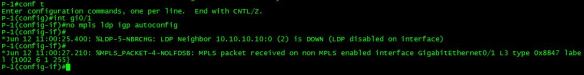
The final step in bringing up the MPLS process is to enable it on the interfaces of the routers facing each other that you wish for MPLS neighborships to be established. This is done by going into an interface and using the mpls ip command in order to enable MPLS on the interface. Once this is done on both sides of a connection, you will typically see a message indicating that LDP is established:
Example: LDP-5-NBRCHG: LDP Neighbor 10.10.10.20:0 (6) is UP

MPLS LDP Verification
Once I have enabled MPLS on all of my core routers and their interfaces, I use the following commands to make sure that everything looks good.

show mpls ldp neighbor
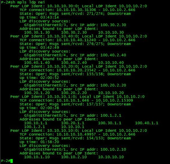
This output shows us all of the LDP neighbors and gives us quite a bit of good information as well.

  • Peer LDP Ident: This is the router-id of the LDP neighbor session.
  • Local LDP Ident: This is the router-id of the local router’s LDP session.
  • TCP connection: This gives us the TCP port information for the LDP session. The number here that is important is 646, which is the TCP port that LDP hellos are initially sent on. The IP address that precedes this is the router that initiated the LDP session. The other number is an arbitrary TCP port that responds on the other router to the initial LDP hello in order to establish the LDP session. The LDP Hello is initially sent out via an all-router multicast of 224.0.0.2. Targeted LDP sessions using a neighbor statement can also be used in order to limit multicast announcements on a link.
  • State: This tells us the state of the link, Oper is what we want to see when the LDP state is operational.
  • Msgs sent/rcvd: This is the count of the number of LDP messages, including keepalives, that have been sent to/from this neighbor.
  • Downstream: This indicates that the downstream method for distributing labels is being used. The LSR advertises all of its locally assigned (incoming) labels to its LDP peer, barring any ACL restrictions.
  • Up-Time: The uptime for this LDP session.
  • LDP Discovery sources: These are the sources (Interfaces/IP) that were the source for the establishment of the LDP session.
  • Addresses bound to peer LDP Ident: These are interface IP addresses on the LDP peer device. These addresses are a part of the LFIB, and also may be next hop addresses in the local routing table.

show mpls ldp discovery <detail>
show mpls ldp disc

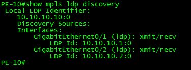
This command gives us a nice and concise insight as to the interfaces that LDP peer sessions have been established on, along with the LDP ID of the neighbor on that interface. The detail command gives additional information that is especially useful when troubleshooting timer and other negotiation problems.
sh mpls ldp discovery det
As you can see, this tells us much more information on the LDP peer sessions, along with timers, and whether or not a password is required or in use. I’ve found this command especially useful when working on troubleshooting, or if I need to modify timers and determine if both sides have the same timers configured.

show mpls forwarding-table
sh mpls forwarding-table
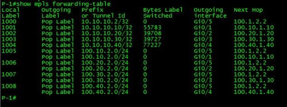
The MPLS forwarding-table is also known as the LFIB. It is very useful, as it contains a wealth of information when it comes to determining how a labeled packet is handled when it comes into the router. The first column, Local Label, is the label that this router expects to see on a packet that arrives. This is the top label, when we have multiple labels on a stack, and is the only one that this router will be interested in. Since the router we are looking at is a P router, and the way this lab network is built, all labels outbound from it will be at their destination, the Outgoing Label column for all of these labels will be Pop Label. If we had multiple P routers in the LSP, we would see a label in the Outgoing Label that corresponded to the Local Label of the next-hop router for that LSP, and the Local Label would be swapped with that label, and then forwarded out the outgoing interface. The outgoing interface and next hop columns are information that is contained in CEF for the prefix that we are trying to forward the packet to.

There are quite a few other commands that are useful, but for the initial configuration, those are the three that I rely on to make sure that the LFIB looks good before moving on to the next step, which will be to build a BGP VPN network between our PE routers and configure VRF’s on the PE’s to connect to the customer networks. That will be the next in this series of posts.

Update: June 2017

Ok, it’s been far too long since I’ve posted anything on this page, and all I can say is that the CCIE has been the most all consuming study process that I have ever been through in my life. I finally decided to book my lab for September 11, 2017, which gives me roughly three more months until I will sit the lab for my first (and hopefully only) attempt. I have been getting in 25-30 hours of lab time in per week, and I’m hoping to up that to closer to the 40 hour per week range as the lab approaches.

My study plan at this point has been doing lots of full scale labs, along with working through Narbik’s Foundations and Advanced Foundations workbooks. I attended Narbik’s 10 day CCIE bootcamp in early April, and it was easily the best class that I’ve ever been to. He is an amazing teacher and all around awesome guy, and if you can swing it, I highly recommend attending if you are serious about the lab. I know he offers a pretty hefty discount for military (active and retired) members, so make sure you mention it to Janet when you sign up.

Lastly, it is getting close to Cisco Live 2017 in Las Vegas. We’re just a little over three weeks away from the kickoff to my favorite event of the year. This year, I’m participating in TFDx at CLUS, which is Tech Field Day at Cisco Live. This year, they’re having separate groups on Tuesday and Wednesday, and I’ll be a delegate on Tuesday. It’s an entire day of Cisco presenting, and I’m looking forward to hearing them along with reconnecting with some TFD friends and meeting a few new people.

The final portion of this update is a challenge to myself. I’m hoping to begin to add more content specific to the final process of preparing for my CCIE lab. I’m going to start to add more content specific to pieces of the blueprint that I found difficult or interesting, along with screenshots and other fun stuff. This is in hopes of helping me be accountable to not only getting content created, but hopefully learning more about the process by posting my thought process on the site. Short update, I know, but more will be coming soon. I’ve already started the process of creating a 20 node lab in VIRL, and I’m hoping to share that soon.